适用于计量室、生产、来料检验和开发质量控制的高效优质计量技术。
齿轮泵和混配系统,以最高精度处理液体和糊状物。
用于无间隙线性和旋转运动的高精度旋转冲程轴承,可用于机器和设备制造。

德国马尔【Mahr】我们引领测量技术、滚珠导轨和计量技术的开发与制造已有近 160 年历史。


创新的计量学,应用范围广泛:
- • 长度和直径
- • 表面和轮廓
- • 形状和位置
- • 齿轮和轴
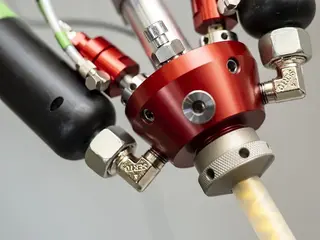
液体和糊剂的精确混合与计量:
- • 齿轮计量泵
- • 纤维生产用泵
- • 计量混合分配机以及混合头
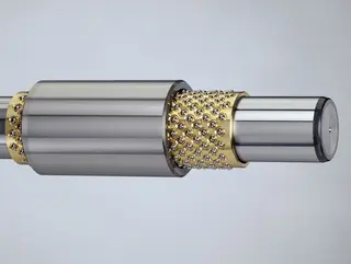
用于以下行业无间隙线性和旋转运动的转冲程轴承:
- • 机械工程
- • 精密工程
- • 光学
- • 电子
- • 以及许多其他行业


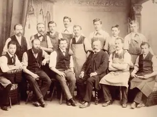


作为一家活跃于国际范围的公司,Mahr 不仅在德国拥有专利,在世界范围内也拥有专利。

Determination of centering errors and tilting of aspheres
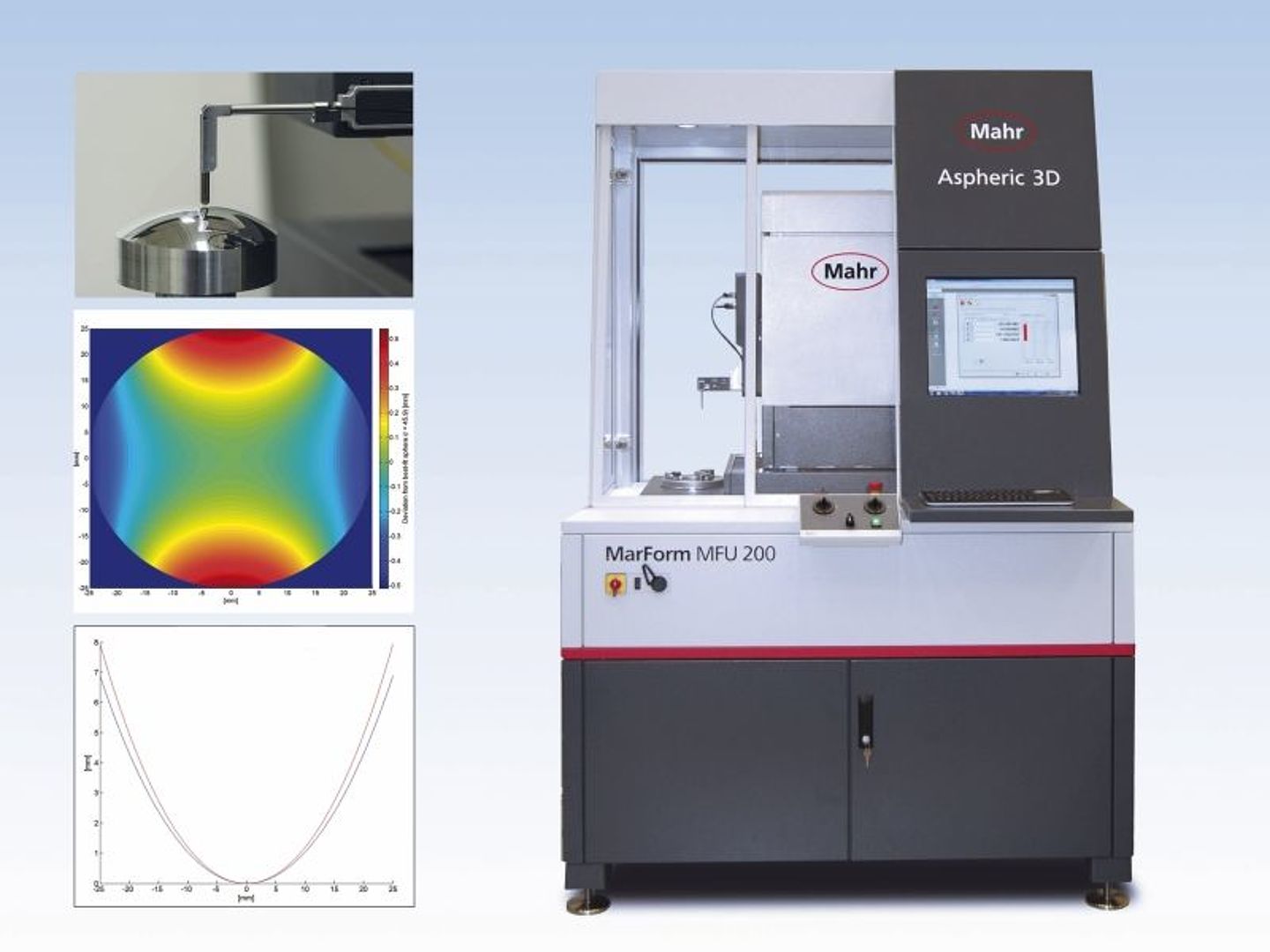
Software package MarWin Aspheric 3D
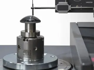
The package together with theMarForm MFU 200 offers the possibility to display the topography of optical components, such as aspheres.
Measuring principle
For the 3D measurement, two linear profiles, which are offset by 90°, are first measured over the zenith of the lens. Subsequently, a several concentric circular profiles are recorded by rotating the C-axis. These measuring points are used to generate a topography. The free positioning capability of the probe arm makes it possible to measure interrupted surfaces.
Of course a fast 2D measurement can also be recorded with a stylus over the zenith of the lens.
Through the use of the measuring station in a vibration-damped cabin, external disturbances, such as vibrations and dirt, are kept away from the measurement objects.
Measurement sequence
Before the measurement, select the nominal shape type and set the parameters of the expected target lens. In the next step the measurement data are recorded and compared with the nominal data of the lens.
The RMS value, the PV value and the slope error (slope error) are displayed as parameters.
In the software, the individual parameters such as the radius of curvature R0, the conical constant k and the aspherical coefficients Ai can be adapted for the aspheres when fitting the nominal asphere into the fit asphere.
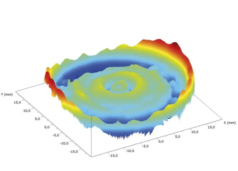
The differential topography between the determined measured values and the desired lens is output as a color-coded height image. The 2D sections and the differential topography can then be exported in known formats for correction to the processing machine.
In addition to the measurement of spheres and aspheres according to the above-mentioned description, other rotationally symmetrical objects can also be measured and evaluated with the aid of the nominal shape as a conical section or arrow height description or a 3D point cloud.
Combined opto-tactile measurement
In order to accurately examine and ensure the optical performance of a lens, it is often necessary to measure, in addition to the surface geometry, the relations between the front, back and edge.
One way of determining these parameters is to detect the position of the mechanical axis of the lens edge and the tilting of the rear side relative to the optical axis of, for example, an aspherical surface. The entire measuring sequence is carried out in one clamping in a fully automatic measuring sequence and with the use of different probe systems.
Click here to download an application form from the Download Box on right hand side, which provides a solution for a fast and comprehensive measurement of complex measuring tasks with regard to the shape and position of optical surfaces.